Fixture design and calibration process |
Within the JoeScan-provided JSDiag software, the Calibration Editor is used to calibrate the scanner's position and angle. Whenever a scanner is replaced or physically moved, it will need to be recalibrated. In general, it is wise to periodically perform a calibration on all the scanners in a system to ensure they are providing highly accurate measurements.
The calibration schedule will depend upon the level of accuracy required, the amount of vibration the scanners are subjected to and stability of the frame. Calibration schedules can vary from daily to quarterly depending on the user’s needs. System integrators can establish a calibration schedule.
On a lineal feed system, any number of JoeScan scanners are mounted radially around the log so the circumference of the entire log is covered, as shown in Figure 1. The laser planes of all heads are ideally coplanar (at least parallel with very little distance) and the transport direction is perpendicular to the laser plane. In practice, JoeScan scanners tolerate mechanical misalignment well; therefore, mounting does not require precision alignment.
Any of the scanner models offered by Joescan – even a mixed configuration – can be used in a lineal scanning system based on the following factors:
Standoff distance,
Minimum and maximum log diameters,
Accuracy requirements,
Transport speed, and
Mechanical considerations.

Figure 1. Example schematic of a lineal system
A calibration fixture is a physical object with a well-known geometry that is placed in the scanner’s field of view. Based on the data the scanner can “see,” it performs calculations that result in a position and orientation in space, relative to the fixture. This process is what JoeScan calls a “calibration.” Multiple scan heads can be calibrated together (with view of the same fixture) such that all heads share a common coordinate system. As a result, points measured by any of the heads fit together seamlessly, making processing of the resulting points much easier. Each head retains its own calibration until the user recalibrates it.
Calibration fixtures don’t have to look like the example in Figure 2 (dimensioned in Figure 3). However, the calibration fixture should be asymmetrical for two reasons:
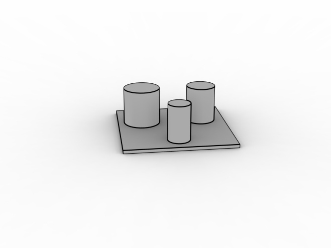
Figure 2. Example calibration fixtures
When making the fixture, it is important that the fixture is designed such that it can be placed in the same position when re-calibrating the system.
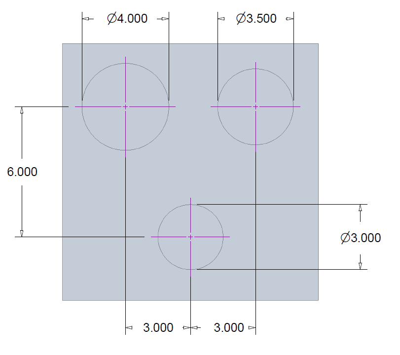
Figure 3. Example calibration fixture dimensions (in inches)
For best calibration results, the fixture should be designed such that it covers a majority of the desired scan envelope. For example, if the largest log diameter to be scanned is 13 inches, the fixture should extend nearly to the edges as shown in Figure 4.
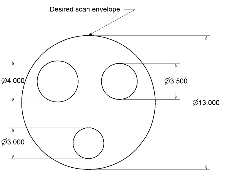
Figure 4. Circles fixture nearly fills the desired scan envelope
The parameters file (param.dat) is used to modify the parameters that control the scanner's operation. Calibration fixtures must be defined within the param.dat file using features. The available features are CircleFeature, SquareFeature and LineFeature. A calibration fixture can be made up of many features of only one type (e.g., many CircleFeature elements with no SquareFeature or LineFeature). You can put many different CalibFixture elements in a single parameter file. A single ScannerConfig can have many different CalibFixture names listed with its CalibrationFixtureNames parameter. At minimum, fixtures should have at least two circle features, one square feature or multiple line features.
The origin of the global coordinate system is determined by two factors:
The way the calibration fixture is defined in the parameters file. Choose an origin on the fixture and measure all features from that point.
Where you place the fixture in the laser plane. It is important that the fixture is stable and that its position in the system is repeatable.
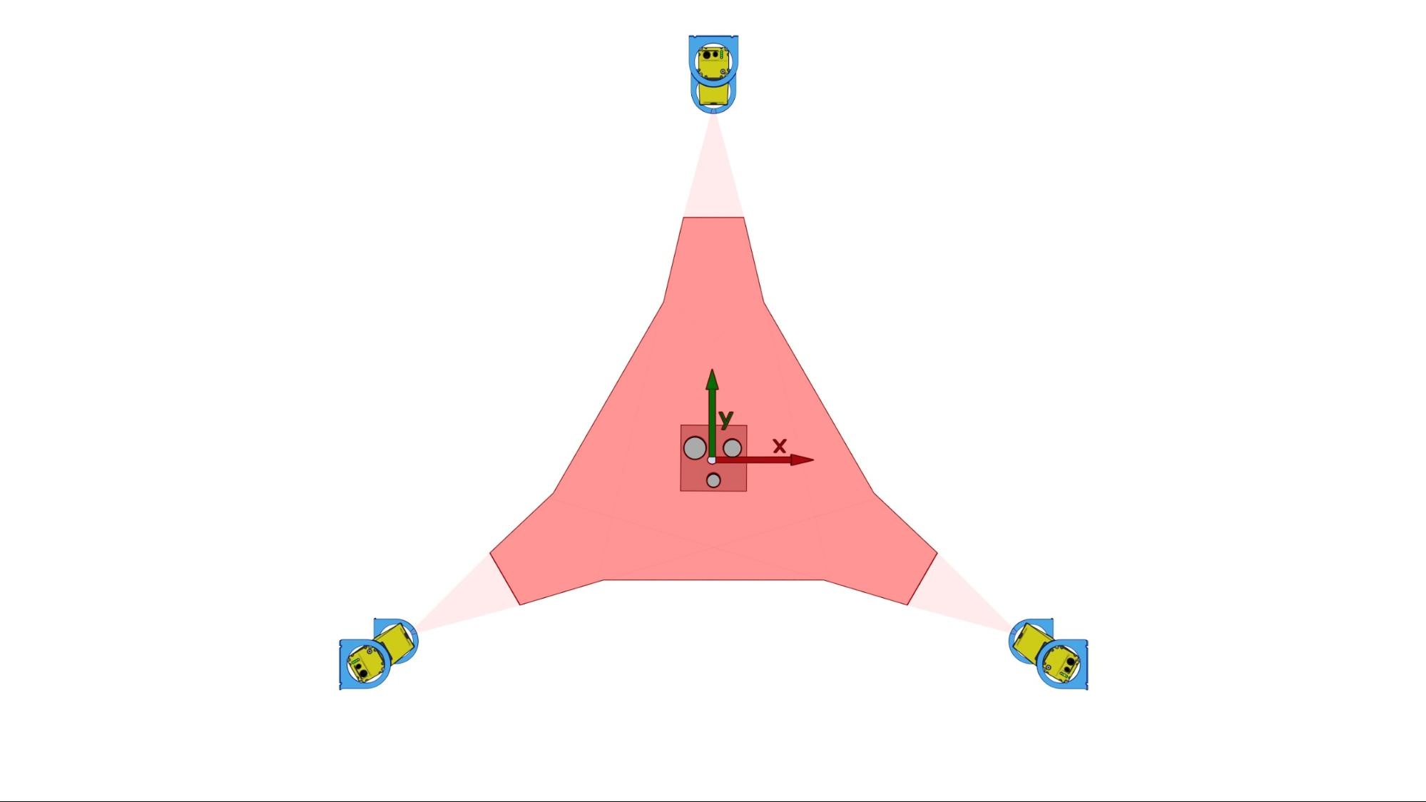
Figure 5. Calibration fixture in the laser plane of a JoeScan lineal scanning system
Example: To set the origin of the global coordinate system, as shown in Figure 5, in the center of the fixture, the parameter file would include the following section:
CalibFixture Circles
{
#         		 Radius   CenterX     CenterY
 CircleFeature   2.001     -3.010        2.990
 CircleFeature   1.755     3.005        3.011
 CircleFeature   1.508     0.0         -3.030
} |
It is important that the fixture is physically measured and the actual measurements are used to describe the features in the param.dat file, for the example radius and X,Y position of the circles shown in Figure 6. The measured radius of the top left circle is 2.001 inches, centered at the coordinates (-3.010", 2.990"). The radius of the top right is 1.755 inches, centered at the coordinates (3.005", 3.011"). The radius of the bottom circle is 1.508 inches, centered at the coordinates (0.0", -3.030"). |
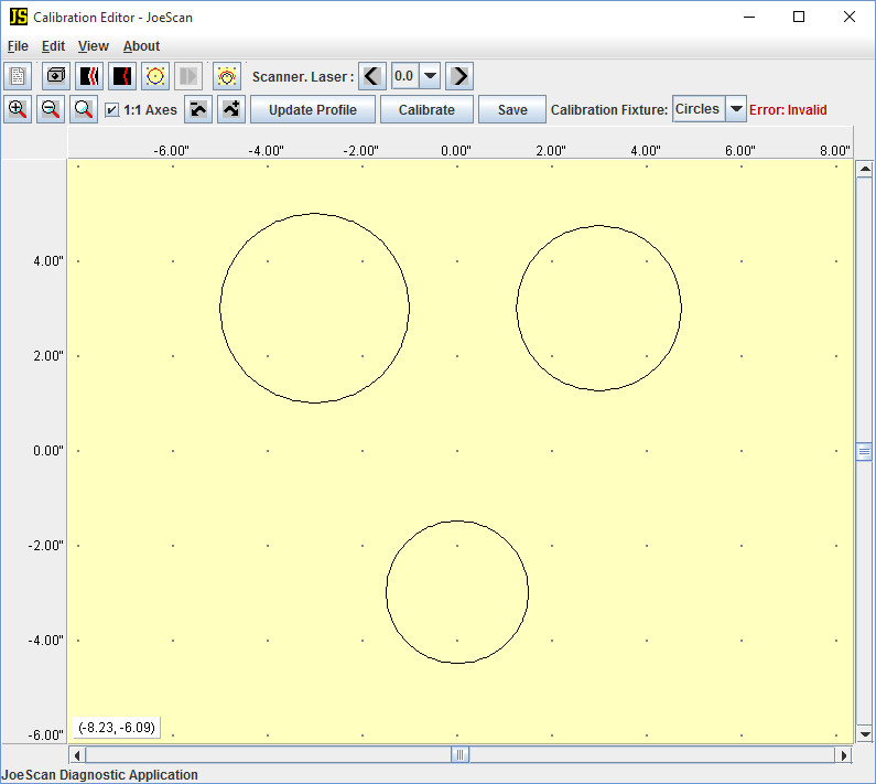
Figure 6. JSDiag screenshot – Circles calibration fixture
Once the calibration piece is correctly defined in the parameter file, follow these steps:
Rigidly position the calibration fixture in the laser plane where all scanners see two or more features, as demonstrated in Figure 5.
Switch to the “Calibration Editor” (F7) window in JSDiag.
Select the first scanner to calibrate from the Scanner.Laser: drop-down box.
Select the appropriate calibration fixture from the Calibration Fixture: drop-down box.
Click Update Profile to show the latest data point profile from that scanner.
In Figure 7, the red data points are from the top scanner from Figure 5.
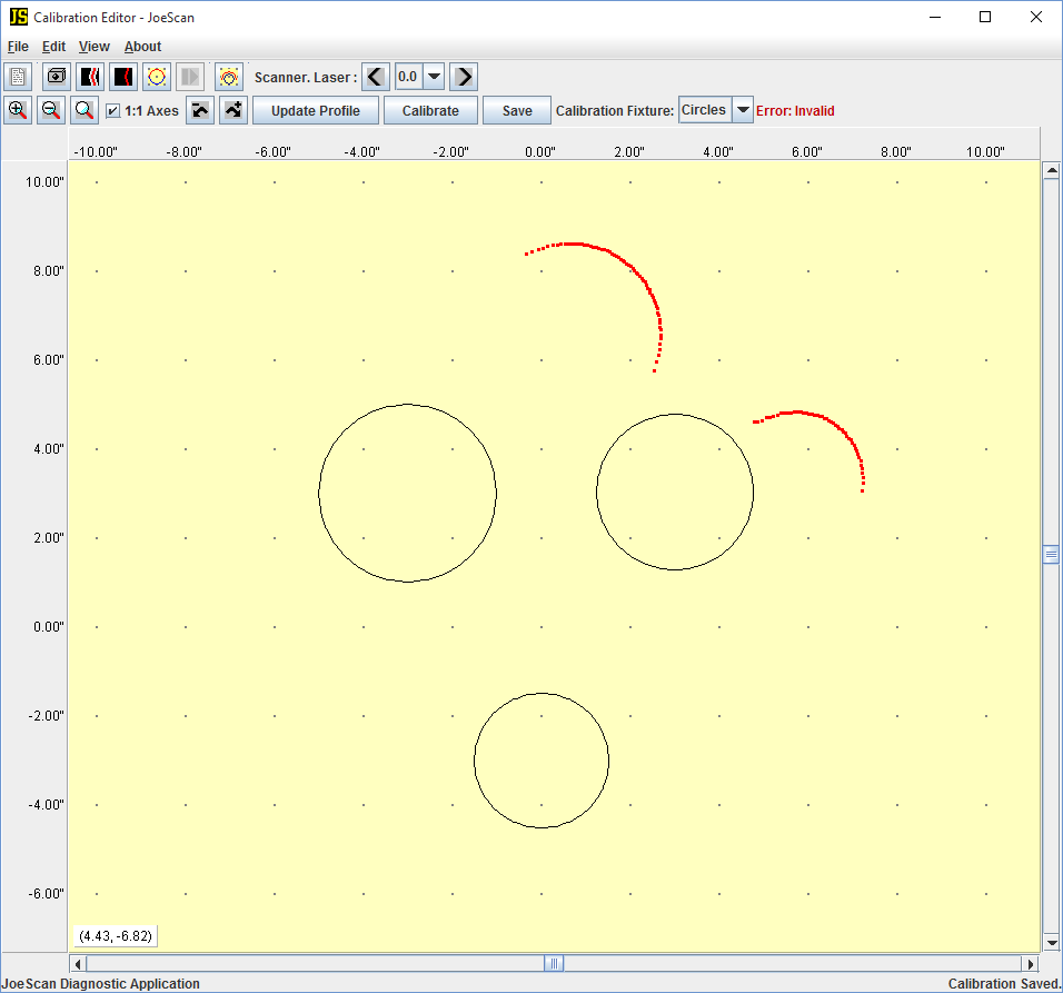
Figure 7. Data points visible from scanner 0.0 (scanner.laser) not aligned.
Move the data: left-click and drag.
Rotate the data: right-click and drag.
Tip: It's easiest to drag the profile to one feature and then use that feature as the center of rotation.
Tip: When rotating, moving the mouse farther away from the center of rotation will make fine-grained rotation easier.

Figure 8. Data points visible from scanner 0.0 (scanner.laser) aligned
For additional examples of calibration fixtures in the Parameter Editor, read the Calibration Parameters documentation .